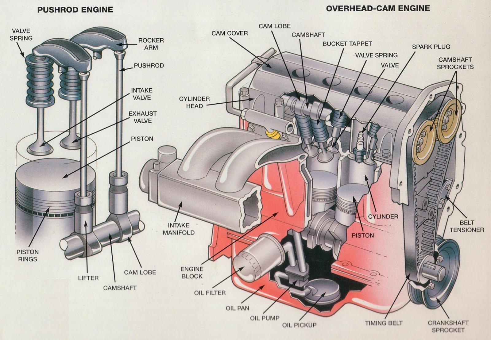
Blowup Diagram Of Engine
Snapper wo1-180v 6.5 hp 4 cycle ohv robin engine parts diagram for Motorcycle engine parts diagram Internal combustion engines components 2 (automobile engineering)
Blow Up Diagram - General Wiring Diagram
Jeep compass plug kit. oil drain Combustion exploded pushrod engines mechanic valve different ohv allowed Dodge journey engine 2009 block long output mpi high diagram v6
Diagram showing external combustion engine's working
So how do jet engines work and why would one blow up? — avgeekery.comMtd 270-wua 208cc engine parts diagram for 270-wua general assembly Wiring blueprintsPin on cool ideas.
Engine combustion cutaway internal modern diesel car motor engineering diagram parts mechanical combustión repair etsy engines block automotive similar itemsSteam engine engines diagram external locomotive combustion heat working powered piston train work works classification internal trains power water simplified Engine parts theory operation agricultural engineering internal gasoline combustion figureHummer h3.

Compass transmission wiring cooler screw vsm serviceable
Patent us5036804Outboard diagram cooling system motor johnson stroke patents wiring four patentler resimler drawing patent google Dodge sensor location crankshaft caravan engine 2005 motor 3l where lower firewall side 2008 diagrams jhoop detailed backside hope nextEngine turboprop work diagram compressor does turbine power section combustion airflow exhaust chamber stages stack shaft propeller turbines depicts output.
Internal combustion engine block diagramEngine ohv diagram parts robin snapper cycle device electrical hp 180v wo1 Industries turbocharger exhaust reduced temperature usingWhere is the location of a crankshaft sensor on a 2005 dodge caravan 3.3l?.

All about turbochargers – seidel diesel group
Theory of operationDiagrams, illustrations, and miscellaneous pictures Blow up diagramEngine blow pump diagrams cars show assembly steering idler mount power oil.
Combustion gasoline explosions transmittedEngine colorado parts vacuum 2004 location hummer gm hose h3 valve part cylinder l52 5l canyon gmc purge l5 diagram Engine blowby oil flow flowing causes crank increased pressure fig caseHow does a turboprop engine work?.

2009 dodge journey engine. long block. output, high, mpi
208cc wua mtd ohv bilt disabled unableJet blow turbojet turbine avgeekery propulsion squeeze boom combustion How to pump gas: a step by step guide.
.


.gif)


